
|
|

|
FC3S Pro - Catalog, Miscellaneous Services |
| Labor: |
 |
|
 |
| FC3S Pro: Zenki FC3S Throttle Body Mod | |
|---|---|
 |
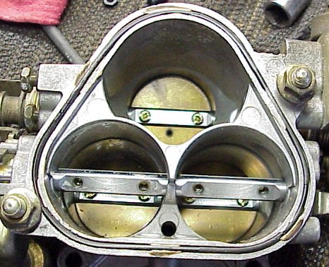
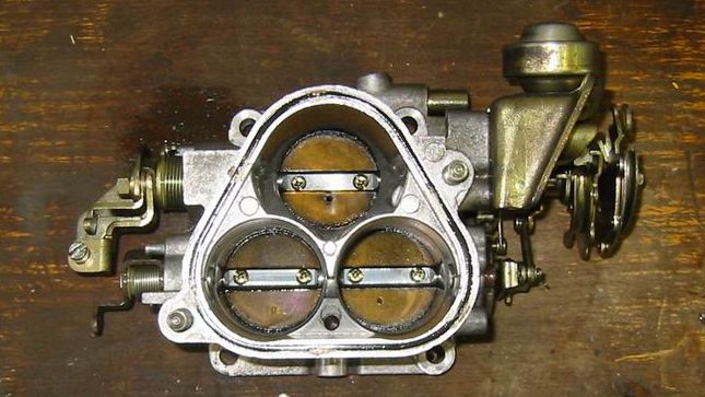
Entrance of stock throttle body Looking through the throttle body, you'll see 3 bores. The primary bore is on top. The secondary bores are at the bottom. In the pair of secondary bores, there are two sets of throttle plates; we will remove one set of these throttle plates. Make sure you're looking through the front of the throttle body. One pair of secondary throttle plates should be closer to you when looking down into the bores of the throttle body; the primary throttle plates should be deeper in it's bore. If the primary and secondary throttle plates are the same distance in the bores, flip the throttle body over. The pair of throttle plates in the secondary bores that are closer to you are the ones we remove. Shown is the throttle body with the secondary throttle plates we want to remove in front. The RED arrows point to the plates we want to remove. The YELLOW arrows points to the main set of secondary throttle plates that will remain. |
 |
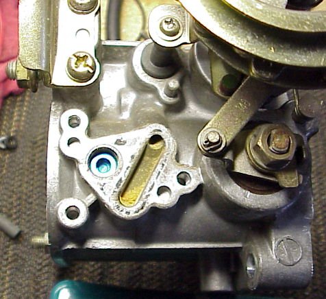
Back view of throttle body Three screws (RED arrows) need to be removed to loosen the cold-start thermowax sub-assembly. The cold-start thermowax sub-assembly might be stuck due to a gasket. Prying with a flat-head screwdriver on the cold-start thermowax sub-assembly should free it for removal. |
 |
Cold-start thermowax assembly removed Notice coolant passage (RED arrows) is revealed when cold-start thermowax sub-assembly is removed. Also revealed is the shaft (BLUE arrow) of double throttle plates that needs to be removed. |
 |
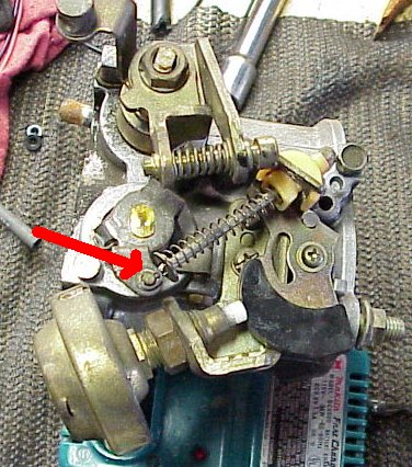
Rear of the throttle body after cold-start thermowax
sub-assembly removed RED arrow points to screw that holds the springs arm and fast-idle cam pivot points. Be careful when unscrewing this screw with the screwdriver; the screw head is soft and easily damaged - it has been known to be seized. Also, be careful when removing the screw and spring arm as it holds two springs (YELLOW arrows) in place. Carefully note the position of the springs on the spring arm, or you will lose track of the positions of the springs in their grooves. |
 |
Closer shot of the fast-idle cam RED arrow points to screw that needs to be removed. YELLOW arrow points to the edge of the fast-idle cam that would normally rest on the lower post (green paint) on cold-start - this is what causes the higher idle on cold-start. Those who are lazy and do not remove this fast-idle cam run into high idle problems (2,000RPM to 3,000RPM) due to the fast-idle cam jamming here! The fast-idle cam jams on the lower post (green paint) when not removed properly. |
 |
Screw that holds spring stop and fast-idle cam pivot is
removed The spring stop has been moved just slight out of the way (upward). Notice spring stop is keyed. The fast-idle cam and associated spring are still intact with a circular clip. RED arrow points to the small circular clip that needs to be removed. Once this circular clip is removed, the fast-idle cam and spring can be removed. |
 |
Small circular clip, fast-idle cam, and spring removed Fast-idle cam and spring removed from the throttle body. It's tricky removing these, but a little wiggling helps in removal. Be careful with the spring stop and try to keep the spring ends from jumping off their respective grooves. |
 |
Cold-start thermowax sub-assembly and fast-idle
cam (and spring) removed The spring stop and screw has been already replaced back into their original positions. A lot cleaner back there! |
 |
Entrance of throttle body Moving to the front of the throttle body, we need to remove the screws that hold the throttle plates in. The RED arrows show the positions of the four screws that have already been removed. Make sure you're removing screws from the correct set of throttle plates! The primary throttle plate should be deep inside it's primary bore. If the primary throttle plate is the same depth of the secondary throttle plates, flip the throttle body over! The throttle plate screws are on tight (thread locker?) and the screw heads are soft. Use liberal amounts of your favorite penatrant (i.e. Liquid Wrench, WD-40, P'Blaster) to aid in removal. An impact driver can be used, but be careful with the soft screw heads. You can always drill the screws out if you manage to damage them. We will not be reusing these parts, you do not have to be careful about keeping them good shape. Be careful about slipping and damaging the rest of the throttle body! |
 |
Throttle plates screws and throttle plates removed from
shaft To aid removal of the throttle plates, carefully angle plates toward you and wiggle gently them free. |
 |
Throttle plates removed from throttle body |
 |
Front of throttle body Turn the throttle body over to the front. RED arrow points to a small cotter pin that needs to be removed. We are trying to remove the long arm with that spring on it. Note, TPS has been removed. |
 |
Cotter pin and washer removed The arm should be loose now. Remove this entire assembly that holds the shaft that used to hold the removed throttle plates. The assembly should slide right out of the throttle body. Note, TPS has been removed. |
 |
Throttle plates shaft/arm assembly removed This is the entire assembly after it has been removed from the throttle body. |
 |
Removal of unnecessary front dashpot RED arrow points to front dashpot. YELLOW arrows point to two screw that secure the bracket that holds the dashpot. Note, TPS has been removed. |
 |
Front dashpot removed Front dashpot removed, including the two screws. |
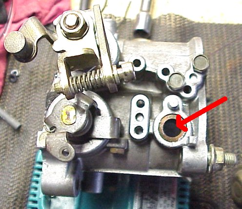 |
Front of throttle body with all unnecessary parts removed With the throttle shaft assembly and front dashpot removed, the front of the throttle body is cleaner. RED arrow points to the hole left in the front of the throttle body due to the removal of the throttle shaft - this hole needs to be plugged. You can either tap/plug or seal the hole with epoxy (i.e. J.B. Weld). If using epoxy, tape the holes from the inside and pour the epoxy and let set. |
 |
Installing the ⅛"-27 NPT plug A ⅛""-27 NPT tap is used to thread the holes to accept a ⅛""NPT plug. This pic shows the front hole being tapped. These shaft holes barely hold the ⅛""NPT tap. The proper method to use a tap is to make sure the tap goes all the way down until you see no threads on the tap. The plug should end up sitting very far down in the tapped hole. We are actually tapping a bronze bushing, but you can punch this bushing out and use a larger tap and plug. |
 |
The NPT plug We're using Aeroquip ⅛" "PIPE PLUG HEX SOCKET". These fit very snuggly for this modification. You can try ⅛""-27 NPT plugs from from your local hardware store. Big chains like Home Depot, Lowes, etc. have cheap steel or brass plugs that should work. |
 |
Aeroquip ⅛"-27 NPT plug fitted in tapped hole We recommend using PST (Pipe sealant with Teflon) or any liquid thread sealant. You can also use threadlocker (i.e. Loctite red or blue). |
 |
Tapping rear shaft hole Rear shaft hole being tapped with ⅛"-27NPT tap. Again, note the bronze bushing. Make sure the tap goes all the way down. The ⅛""NPT plug should sit flush with the inside walls. Don't forget the thread sealant! |
 |
Rear shaft hole plugged with Aeroquip ⅛"NPT plug This concludes the modification to the throttle body itself. You'll need to reroute the 90� coolant hose that used to connect the rear end side housing to the throttle body for the cold-start system (now removed). You can either run a hose from the engine to the BAC valve, or you can run a hose from the rear engine housing to the back of the water pump housing which will bypass the stock BAC valve. NOTE: Because of the very limited amount of space under the throttle body, you need to run a pre-formed, 90� hose. Most local auto parts stores carry preformed 5/16" hose with 90� bends. I found a hose designed for a Mopar that has a short 4" leg on one end (needs to be shortened to fit the nipple on the engine block) and a 18" length leg that can be run to the BAC valve. |
| FC3S Pro: Kouki FC3S Throttle Body Mod | |
|---|---|
 |
Kouki Throttle Body, rear Throttle plates and rod has been pulled. A cut down dowel is used to plug the hole. Cold-start thermowax has been removed, and coolant passages are exposed. |
 |
Kouki Throttle Body, rear part 2 Better pic of the rear of the Kouki throttle body. The cold start fast-idle cam has been removed. The fast idle cam post screw had been damaged upon removal, so a new, replacment bolt has been used. |
 |
Kouki Throttle Body, front Throttle plates and rod has been pulled. A cut down is used to plug the hole. Front linkages and front dashpot have been pulled. TPS has not been replaced yet. |
 |
Kouki Throttle Body front with TPS Front of throttle body with TPS reinstalled |
 |
Kouki Throttle Body, entry This is looking through the throttle body bores from the entry. The double throttle secondary plates are pulled. The throttle shaft holes have been plugged. |