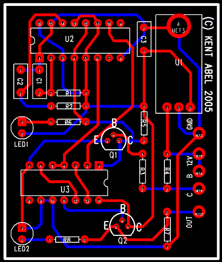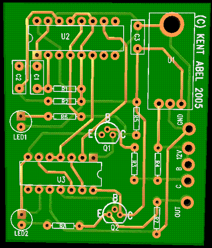

v2.1 Auto-switching with max pulse limiting
PCB


Parts List
U1 7805 5V Voltage Regulator
U2 MC14538B Dual Precision Monostable Multivibrator -
DATASHEET
U3 74HC00 Quad 2-input NAND gate -
DATASHEET
Q1-Q2 NPN General Purpose Transistor (2n2222A or equivalent)
C1-C3 0.1uF Capacitor (ceramic, metallized polyester film, etc.)
R1 22k Ohm resistor �-watt (sets 2.2ms minimum value)
R2 ~40k Ohm resistor �-watt (sets 4.0ms maximum value)
R3 22K or 33k Ohm resistor �-watt
R4, R5, R7 1k Ohm resistor �-watt
R6, R8 330 or 390 Ohm resistor �-watt
LED1, LED2 T-1 LED (green, red, amber, etc.) blue, white, and similar
will not work because they require a higher forward voltage
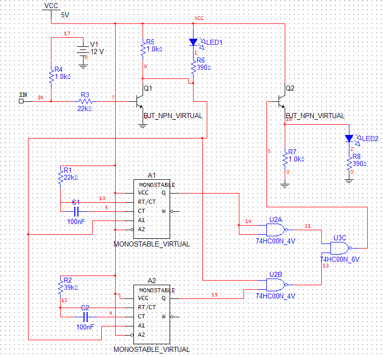
Circuit Diagram (Simulation Screenshot - SEE NOTES!)

Diagram Notes:
- Component labels above now match component labels on PCB and Parts List
- The type of multivibrator used in the simulation has an output
pulse of 0.7*Rx*Cx instead of tx=Rx*Cx like the one used in the real
circuit. I increased capacitance in the circuit to account for the difference.
- The output of the circuit is at LED2 (emitter of Q2)
- The real NAND gates get 5volts instead of 4volts as shown on the layout.
- The NAND gates should form an AND function between the input pulse and the max
pulse. The output of this AND function is then OR'd with the 2.2ms pulse. This
should bound the output pulse between 2.2ms and 3.9ms.